Supplies
| Item | Details | Approx. cost | Example |
|---|---|---|---|
BeamsplitterRequired | Central component of the interferometer. Main requirement is that it’s decently flat and splits light at close to a 50/50 ratio. Many options. Spending more money usually gets you bigger and more flat. Having a cube is nice as it eliminates the need for a compensation plate in the interferometer (a complexity which is not discussed in this guide but you can find mention of this on Wikipedia). Cubes are also often visually easier to explain to attendees. Pricey new, but there should be many eBay options floating around if you look. | $50–$100 used$100–$350 new | Fancy cube from Thorlabs |
2× mirrorsRequired | Central components of the interferometer arms. Must be first-surface, quite flat, and not terribly lossy. | $60 each new | Thorlabs |
Kinematic mirror mountsRequired | To align the mirrors on each arm of the interferometer. | $45 | Thorlabs |
Laser sourceRequired | Light source for the experiment. It is possible but quite challenging to do with laser pointers — a HeNe laser is extremely highly recommended. | $150–$300 | Light sources |
Viewing screenRequired | To see the output patterns. | $0–$10 | Optomechanics |
Microscope objectiveHighly recommended | Multiple purposes. First, when using the HeNe, it’s a simple way to expand the beam so the interference can be seen over an area instead of a point. Placed before the interferometer, it lets you see circular “fringes of equal inclination” when the interferometer is imbalanced. | $20–$30 | Amazon |
Translation stageRecommended | Makes balancing the arms of the interferometer tremendously easier. Balancing the arms is required if you want to observe white light interference patterns, and doing so to the required accuracy (±2 µm) without a translation stage is effectively impossible. | $50 DIY$100 used$250 new | Thorlabs |
White light sourceOptional | Allows white light interference patterns to be viewed. This is the most visually interesting part of this demo! If doing this, we strongly recommend laser excited phosphor (LEP) flashlights, but simple white LEDs can also be used. | $10 LED$100 LEP | Light sources |
Iris/small apertureOptional | Improves output pattern clarity when using a white light source. | <$5 DIY$75 new | Thorlabs |
Photodiode and oscilloscopeOptional | Provides a much more deterministic way to align the interferometer if you are trying to do it with an LED or other broadband source instead of an LEP source. | $100–$500 | |
Canned airRecommended | The jet of air from one of these generates very nice patterns when inserted in the interferometer. | $10 | Amazon |
Optomechanics and breadboardHighly recommended | This setup benefits from off-the-shelf hardware and a breadboard to do experiments on. See our recommendations for items suited to a wide range of demos. If you have no such components, a DIY breadboard and mounting hardware can still work, for much cheaper! | <$100 DIY$500 fully off-the-shelf | Recommendations |
Alignment
This section provides a quickly-written and somewhat rambling overview.1 It uses terminology and references some information which may be confusing if you are not yet familiar with the working principle of the interferometer, so checking out the next section may be helpful before going through the alignment procedures here.
We also have this old document from a “crash course” we hosted for a different student organization at UCSD which explains the alignment process for a similar Michelson interferometer setup at the very end. This one provides a much more visual description of the monochromatic alignment process and may be easier to follow, but does not provide any information about the white light alignment process.
Monochromatic alignment
- Place the HeNe laser and align it to the breadboard (level and parallel to the grid of holes; using two irises, or one that you move, is the best way to do this).
- Now is a good time to set the height of the microscope objective for use later. First, make sure you have the laser shining on some sort of height reference (it could be shining through an iris, or you can shine it on a viewing screen and mark the point with a pencil). Place the microscope objective in the beam about 10–20 cm from the viewing screen — you should see quite a large spot on the screen. Tweak the height of the objective until the large spot is centered vertically on the height reference, and tighten down the height adjustment. Set the microscope objective aside.
- Place the beamsplitter and adjust its rotation until the parasitic reflections off its surface reflect back towards the laser. Adjust its height/side-to-side position until the beam from the HeNe is as centered on the beamsplitter as possible (having it centered on the optical path improves the quality of the interference pattern later, as the beams coming from the two arms of the interferometer will overlap with each other the best).
- Place the first mirror of the interferometer (it doesn’t matter much which), and adjust the tip/tilt until its reflection is also reflecting back towards the HeNe. Once again, center the narrow beam on the mirror as well as you can.
- Place the viewing screen at the output. Right now, you should see just one bright spot on the screen, from the mirror you put down (though there may be several dim spots as well if you’re using beamsplitters that don’t have a good AR coating).
- Place the second mirror, taking care to place it the same distance from the beamsplitter as the first mirror is (if you’re planning to do white light patterns, make sure one of the mirrors is on a translation stage). Center the surface of the mirror on the beam. Look at the viewing screen and adjust the tip/tilt of the second mirror until its bright spot lands on the bright spot coming from the first mirror. As soon as you do this you should see the two spots begin to interfere a bit, but it may not be obvious yet.
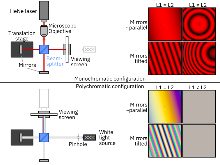
- Place the microscope objective between the HeNe and the beamsplitter. The height should already be right if you performed the earlier process — all you need to do is ensure the beam from the HeNe is going through the objective straight, and slide it side-to-side to center the (now much larger) beam on the optics you’ve already placed. You should be greeted with an interference pattern very similar to the one shown in the “mirrors tilted, L1 ≠ L2” case in the diagram above. Congrats!
- You can now adjust the tip/tilt of either of the mirrors to center the circular fringes in the image projected by the interferometer.
Roughly balancing the interferometer
- The first step to balancing the interferometer uses the circular shape of the fringes (see diagram) as an aid. These circular patterns (“fringes of equal inclination”) appear only when the light incident on the interferometer is not collimated and the interferometer’s arm lengths are not balanced. The pattern will have a smaller looking central circle for greater arm length imbalances and also for more divergent beams.
- Given the above fact, we can balance the arms with moderate precision simply by adjusting the axial position of the mirrors (hopefully, with a translation stage) until the circular fringes become so “big” that they no longer look round. To get an idea of this behavior, play with L2 on this preset of our interactive Michelson interferometer simulator. Notice what happens when L1 = L2 — the fringes change from circles to being totally straight.
- When adjusting the translation stage to achieve this, typically if you’re going in the right direction, as the circles get bigger, you will eventually stop seeing the center of the circle/it will fall off the edge of the image. We recommend periodically adjusting the tip/tilt slightly to re-center the circle before continuing to adjust the translation stage.
- You will eventually reach a point where the fringes neither look linear nor circular, but rather some less ideal/messy shape — a hyperbola or three-lobed shape is common. Once you’re here, the arms are very close to balanced, within 10s of µm of exactly balanced.
Reconfiguring for white light and precisely balancing the arms
- If you’ve arranged the setup in the same manner as our drawing shows, all you need to do here is move the viewing screen to the other side of the interferometer (directly in front of the microscope objective) and set up the white light source.
- When placing the white light source, place it as far away from the beamsplitter as possible (if you place it too far and are using a white LED/point source, the light actually going through the interferometer will be quite dim, so there is a balance here). We recommend passing the white light through an iris to increase the spatial coherence of the light incident on the interferometer, which will drastically improve the sharpness of the interference patterns (in exchange for lower brightness).
- Adjust the position and tip/tilt of the white light/pinhole until the beam is centered on the beamsplitter as well as the mirrors. The next steps depend on whether you are using an LEP source or a more generic broadband source.
- If you’re using an LEP source, as soon as the light is going through the interferometer, you should see faint yellow and pink stripes on the screen. This is yet another property of the LEP source which makes it super nice for this setup.
- Fine tune the tip/tilt of one of the mirrors to flatten out the fringes, making them as large as possible.
- Slowly and gently move the translation stage in one direction, keeping track of the position of the stage knob you started at. If you’ve gone 50 µm and don’t see colorful patterns, turn around and go 50 µm the other way. If done slowly and carefully, in our experience you are guaranteed to find the colorful fringes.
- If you’re using a white LED or other lamp, you will see absolutely no fringes until you’re within about 2 µm of perfectly balancing the arms. You can see this yourself in the simulator here. If you have gotten the mirror tip/tilt real good in the monochromatic step, it is possible to scan the stage extremely slowly ±50 µm from the “roughly balanced” position and you will see the colorful fringes suddenly appear. We have found that this is by no means guaranteed. One method which we have found to work:
- Replace the viewing screen with a photodetector that has an analog output (you could literally use a cheap photodiode with a resistor across its terminals) fed into an oscilloscope. The smaller the area of this photodiode, the better. Make sure to check it works by shining other light sources at it and seeing the signal on the scope.
- Put the scope on “screen” or “rolling” mode (so the x axis of the scope is around 1–5 seconds). It is also useful to put the scope into AC-coupled mode and scale the Y axis way up, so even small fluctuations in optical power are easy to see.
- Slowly and continuously turn the knob to translate the stage over a range of ±50 µm around the “roughly balanced” position.
- As long as your photodetector response time is not too slow, when you pass over the perfectly balanced point, you will see a “blip” in the measured output power consisting of many up/down fluctuations of the optical power (congratulations! you just manually recreated how a Fourier transform spectrometer works).
- Once you see this, you can turn around and easily find the stage location where the blip occurred.
- Frequently, once you hone in on the balanced position, you will find that the reason you’re unable to find it without the photodetector method is because the mirrors are just barely tilted, making the fringes have worse contrast (this reduction in contrast is worse if the spatial coherence of your source is poor, as a large area light source “blurs” out all the fringes when viewed without a lens like this). But with the photodetector, you are able to find the fringes, and fix the tilt of the mirrors once you’ve found them (a tilt which may be different from that which you see when illuminating the interferometer with laser light).
Presentation ideas
Main idea
- Sometimes before explaining anything, it’s good to simply show a few examples of how sensitive the output pattern is: bump the table, press on the breadboard, gently touch mirrors.
- If you have the white light interference, it’s your choice whether you do this with the white light or the red light. Doing white light first can lure people in with more pretty patterns, but doing the red light first allows for a more linear progression of the explanation and a nice “WOW” moment when you reveal the colorful white light patterns later.
- For the technical explanation, start with the red laser.
- First, ask the audience if they know what wave interference is.
- If so, great.
- If not, audiences of almost all ages will find it intuitive if expressed in terms of water waves: if two waves collide with each other and are in sync (in phase), they will add up and get stronger. If they are out of phase, they can totally cancel each other out!
- Explicitly mention that light has wave-like properties and can also exhibit interference.
- Ask the audience if they know how small the wavelength of light is.
- Say that in this setup it is 600 nm, less than 1/100 the diameter of a hair!
- Explain what each component is doing, in the order that light progresses through the system:
- The laser emits a laser beam with 600 nm light.
- The microscope objective expands it.
- The beamsplitter breaks it into two paths.
- The mirrors reflect the beam back where it came.
- The beams recombine at the beamsplitter. This is the most critical part of the explanation and one where people most frequently get lost.
- We recommend clearly explaining what happens to the light from each arm one at a time. E.g., block Arm 2, and clearly explain that the light returning from Arm 1 splits again at the beamsplitter, with one beam going towards the source and another beam going towards the viewing screen. Then, block Arm 1, and show that the same thing is happening with Arm 2: half of its light is going towards the source, and the other half is going towards the screen.
- State explicitly that we will only look at what’s happening to the light from each arm that’s going towards the viewing screen (see Subtle tidbits).
- When these two waves get superimposed on top of each other, they can interfere just like any other wave. Where they are in phase, they add, and where they are out of phase, they can subtract, all the way to zero.
- Important to say explicitly: the reason the waves between the arms can be in or out of sync is because light can travel different distances in each arm.
- And because the wavelength is only 600 nm, we can easily see displacements <100 nm.
- When the mirrors are tilted, you get stripes (“fringes of equal thickness”) because different parts of the mirror are literally different distances from the beamsplitter.
- When the arms are imbalanced, you get rings (“fringes of equal inclination”) because (due to the diverging beam) rays of light at the edge of the mirrors literally travel further than rays of light at the center.
- To prove that the pattern the audience sees is due to interference, show that the fringes disappear when one arm is blocked.
- Now, you can return to doing various things in the arms (try to get the audience hands-on with these!) to highlight the sensitivity of the interferometer:
- Pressing on the table to flex the breadboard
- Placing your hand underneath one of the arms to see heat waves
- Blowing air with your mouth or with canned air. If doing canned air, keeping the stream of air very gentle has the best effect.
- Putting a transparent CD case or other transparent piece of plastic in one arm and observing the highly distorted fringes
- Moving the translation stage to show how the fringes “cycle” when the whole mirror is moved. You can also show the difference between the “fringes of equal thickness” and “equal inclination” for more advanced audiences.
White light explanation
- If you’re going to talk about white light interference, it is very good to make sure before people arrive that everything is well aligned. If it isn’t, it’s very stressful to try and find the super precise fringes when you’re on the spot!
- Move the viewing screen from the “monochromatic” configuration to the “polychromatic” configuration and turn the light on.
- If the interferometer is on, the colorful patterns should immediately be visible, and you’ll get WOWs from the audience.
- Ask the audience why there might be colors:
- Answer you’re fishing for: constructive/destructive interference happens when the distance is different by a wavelength. But the distance of a wavelength is different between the colors.
- Show that the fringes change in color dramatically and suddenly disappear when the stage is moved even a small distance.
- We only see strong interference when the arms are balanced, because only a path length difference of 0 is the same phase for all the different wavelengths.
- When the arms are imbalanced, we have a phase difference between the arms of 2π·ΔL/λ. This changes very rapidly with wavelength for any value of ΔL greater than a few wavelengths, so the fringes wash out and we don’t see colors.
- This can be seen clearly by playing with the “center wavelength” slider on this simulation page.
Subtle tidbits
Two outputs
Interference occurs at both outputs, but only the one with the viewing screen is easily viewable in this rendition of the demo (see Opportunities for improvement). This is a good fact to know, but is best saved for if people ask about it, as it complicates the explanation.
Opportunities for improvement
- Add a second beamsplitter between the microscope objective and the beamsplitter which allows the second output of the interferometer to be viewed.
- We still haven’t done a proper investigation/design of the “best” way to utilize a light source with finite spatial coherence. Use of a lens at the output can solve some aspects of this problem, but the flatness of the mirrors becomes more problematic.
- You can send the output of the white light interferometer to a grating and see the spectral fringes (this is why the spectral intensity plots are included on the simulation page). This is quite cool and is particularly mind-blowing to people in optics who have some prior experience with white light interferometers but have not seen this specific effect before.
- Using an actual USB spectrometer for this is even better, but more pricey.
Notes
-
In the words of Pascal, “I have only made this letter longer because I have not had the time to make it shorter.” ↩