Supplies
| Item | Details | Approx. cost | Example |
|---|---|---|---|
Red laser fault finderRequired | Some way to fiber-couple laser light is required. This is by far the cheapest and easiest way, but other laser sources and optics can be used if that is more convenient. | $15 | Amazon |
FC to LC fiber adaptersMay be required | Depends on the connectors on your fibers and laser source. This adapter often comes with red laser fault finders. | $10 | Amazon |
SMF-28 fiber patch cableRequired | At least one fiber that is multimode at the excitation wavelength is required. | $10 | Amazon |
Platform to base things off ofEffectively required | You want all this on some sort of table. An optical breadboard is the fancy solution, but you can just tape things to a piece of wood, honestly. | $10-100 | |
Polarizer / polarizing filmHighly recommended | Using a polarizer to view the output mode pattern is cheap and adds a lot of technical depth to the explanations. | $5 | Amazon |
Polarization paddlesRecommended | This demo can be performed simply by bending fibers by hand, but paddles provide much finer control and permanence (fibers don’t just bend back). Expensive from Thorlabs! But a great opportunity for a DIY 3D-printed project — it’s just a moving piece of plastic. | $200+ | Thorlabs |
50 µm core multi-mode fiber patch cableOptional | Adds a lot to the demo for a similar cost to the other fiber. | $10 | Amazon |
Single-mode 650 nm fiber patch cableOptional | Adds a lot to the demo. Unfortunately these fibers are much more expensive, as they are not used anywhere in telecommunications. | $150 | Thorlabs |
Presentation ideas
Main idea
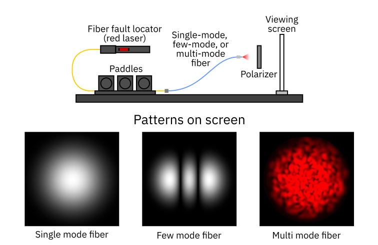
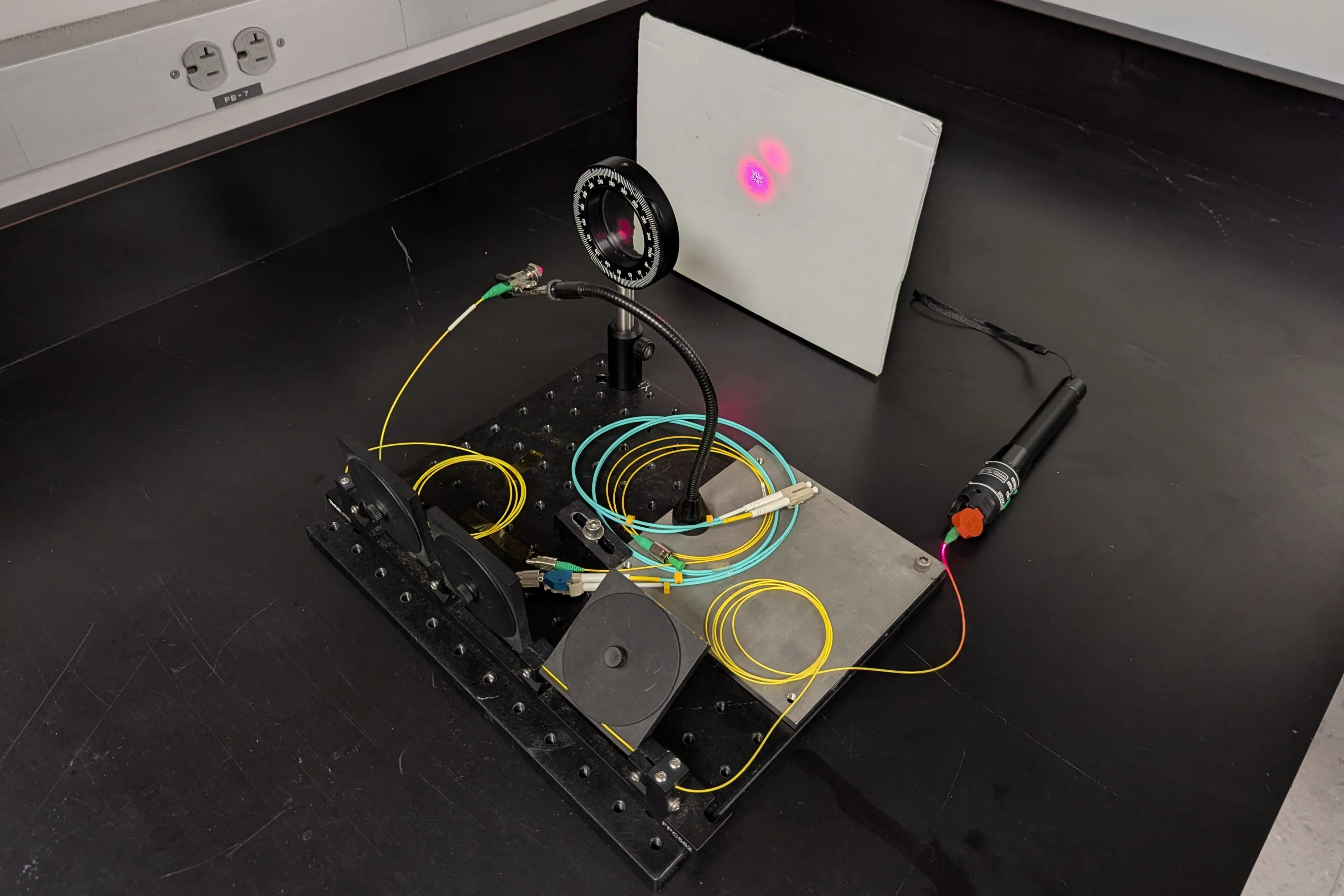
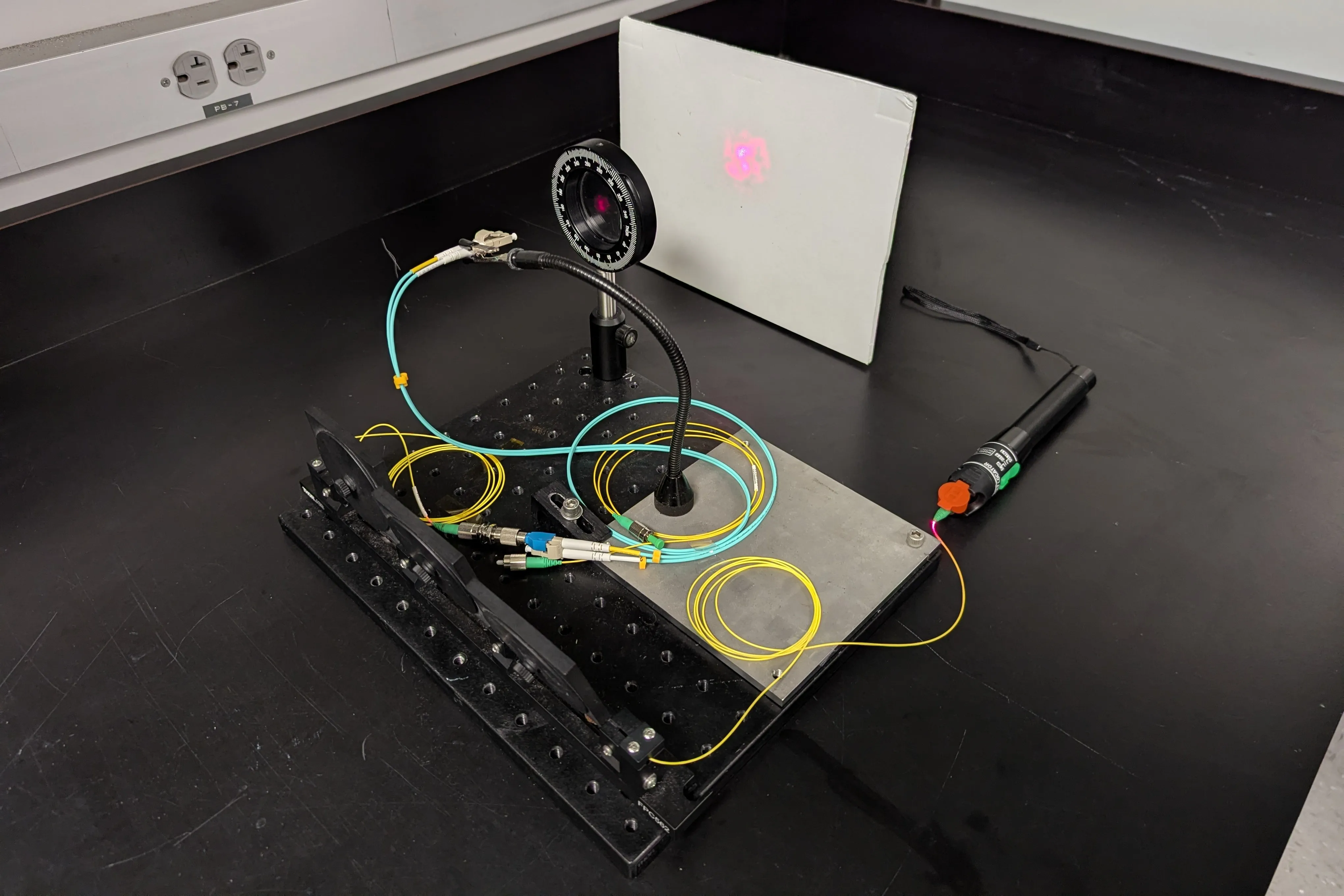
Let attendees play with the paddles or move un-taped SMF-28 fiber and observe the changing intensity patterns on the screen.
- Switching to 50 µm fiber will produce more complex intensity patterns.
- Switching to single-mode fiber will produce an intensity pattern that does not vary spatially as the paddles are moved — only its intensity as viewed through a polarizer changes. Polarization control in SMF is the most typical use case of polarization paddles.
The main concept to explain is that different fibers are suitable for different situations. Large core, multi-mode fibers are much easier to couple light into and can carry higher optical powers, but the unchanging spatial profile of single mode fibers is worth it in many circumstances as well.
Concepts, from simple to complex
-
How fiber works: total internal reflection at the interface between core and cladding.
-
What the different modes in a fiber mean
- Analogy 1: angles of light undergoing TIR
- Analogy 2 (for modes in general): a guitar string
-
What impacts the number of modes a fiber supports:
- A larger core diameter means more modes
- A higher core/cladding refractive index means more modes
- A smaller wavelength in the same fiber means more modes
-
Impact of modes on fiber applications
- Communications: modal dispersion (light from each mode arrives at the receiver at different times, like echoes)
-
Focusing light from a fiber: single-mode fiber light can be collimated like a laser pointer, while multi-mode light becomes progressively harder to collimate (diverges more) as the number of modes increases
-
What the paddles are actually doing
- Why polarization is affected: strain on the fiber induces birefringence, which delays the polarization components relative to each other
- Why modes are affected: bending changes the refractive index and geometry of the fiber, which delays each mode differently (explain either through their different modal profiles or their different angular distributions)
-
Spatial coherence
- More modes = less spatially coherent, with the important note that light is only truly spatially incoherent if the output can only be represented as a sum of modes whose amplitudes and phases vary randomly over the integration time of interest.
- If the integration time is short enough that a snapshot “freezes” the evolution of this mixture of many modes, we can in principle design an optical system that transforms this complex-looking field into a nice-looking beam. This is the basis of adaptive optics, where the pattern is measured very rapidly and a deformable mirror undoes it.
- Many important spatially incoherent sources, like LEDs and sunlight, emit light whose field changes randomly at extremely fast rates (the optical bandwidth of the source, for natural light sources). For almost every practical application the integration time is too long and these fluctuations average out, so no passive optical element can transform the beam back into a single mode.
Gamification
Print out a diagram of Hermite–Gaussian or Laguerre–Gaussian modes. Attendees play with the paddles and polarizer to see if they can reproduce some of the nice-looking patterns on the paper. Recommended with red light and SMF-28 fiber:
- (1,0) modes are the easiest
- (2,0) modes are possible
- (0,0) is possible with some luck and effort
- Many other patterns are possible
Subtle tidbits
- Bend the fiber very tightly and you’ll see more red light leak out. This is because we’re frustrating the condition for TIR — a good lead-in to the minimum bending radius of fibers.
- Try turning the laser fault finder on and off while viewing the multimode intensity patterns. When you first turn it on, the speckle pattern changes rapidly, and if you look closely the changes happen in discrete steps. After the laser has been on for a bit, the changes slow and eventually stop.
- This is the laser diode inside the fault finder mode hopping.
- As the laser heats up, its cavity expands and the frequencies of its modes change. When the lasing mode drifts away from the gain peak, a different mode suddenly begins lasing, causing a step change in the output wavelength.
- The intensity patterns at the output of the multimode fiber are highly wavelength dependent: they come from interference between light in different fiber modes, which travel different optical path lengths. The phase difference between modes is k·L·Δn, so if k changes, the phase changes, and so does the output pattern.
- Accumulating long path-length differences in fiber for interferometry is a very powerful general concept, though doing it in multimode fiber is less common (separate single-mode fibers are more typical).
Opportunities for improvement
- Polarization paddles are one of the most comically overpriced optics supplies I’ve ever seen. You should be able to 3D print them for cheap: fiber polarization controller on Printables.
- Find a cheaper source of single-mode visible fiber. It is a bit niche, but it’s wild that it’s so much more expensive.
- We should make a new demo that actually explains how optical fiber works at a more basic level! For example, one showing total internal reflection inside a large glass rod or stream of water.