Supplies
| Item | Details | Approx. cost | Example |
|---|---|---|---|
Small HeNe laserRequired | Polarized laser source with only one or a few lasing longitudinal modes, each with a linewidth narrower than that of the FP cavity’s resonances. Used lasers like the JDSU 1508 “Novette” can be found at modest cost and reused for many demos — more on our light sources page. | $200 used (eBay)$1000 new (Thorlabs) | Light sources |
Resonator mirrorsRequired | Two mirrors form the Fabry–Perot cavity. They should have a reflectivity near 99% at the HeNe wavelength (outcoupling mirrors) — higher R is not better. We used R = 30 cm radius-of-curvature mirrors. | $35 for 2 (eBay) | eBay |
Tip/tilt optic mountsEffectively required | Yes, it’s possible to align a cavity without these, but you won’t be having a good time. DIY solutions are possible. | $100 for 2 (new) | Thorlabs |
Mirror-to-1″ optic adapterLikely required | Most tip/tilt mounts take 1″ optics, but cheap HeNe mirrors from eBay are typically ~6 mm. 3D print (or buy, if you really want) a plastic ring to adapt them. | <$1 (3D print) | DIY |
Optomechanics and breadboardHighly recommended | This setup benefits from off-the-shelf hardware and a breadboard to experiment on. See our recommendations for items suited to a wide range of demos. If you own no such components, a DIY breadboard and mounting hardware can work for much cheaper. | $500 | Recommendations |
Microscope objectiveRecommended | Enlarges the mode patterns coming from the cavity, which enhances the viewing experience. | $20–30 | Amazon |
Alignment
- Put down the laser and turn it on.
- Put down the second (furthest away) mirror, center the beam on it, and roughly center the back-reflection from this mirror on the incident beam. Make sure the reflective coated side faces towards the laser (towards what will be the inside of the cavity).
- Put the other mirror down at the appropriate distance L from the first (see Subtle tidbits), with the coating facing away from the laser.
- As you align this second mirror to reflect the light back towards the laser, you should start to see the flickering mode patterns at the output.
- Place the microscope objective at the output and adjust the cavity until the patterns look nice.
Presentation ideas
The effect
The images projected by this setup rapidly flicker through a variety of output mode patterns in a way that is visually striking.
Audience
We’ve found this effect is actually more surprising and unintuitive to audiences that already have a decent amount of optics knowledge (late undergraduate to graduate level).
It can be visually interesting for audiences with little optics background, but we wouldn’t make it the only demonstration at an event for early undergraduates or younger. It’s a good choice as the “most complicated” setup for such audiences — something good to look at that showcases the depth and sophistication of optics as a field.
Explaining it
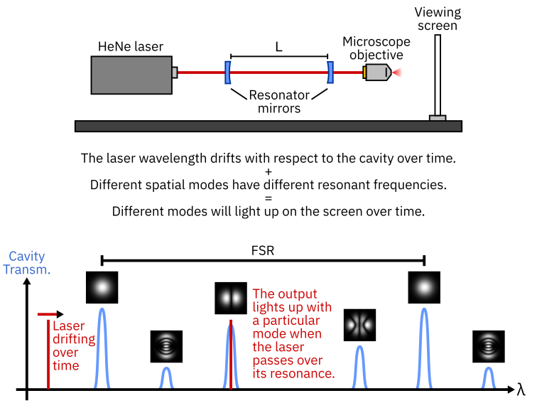
Use the diagram at the top of the page to explain at a high level how the effect works. More detail is in Subtle tidbits.
Hands-on
Let attendees turn the HeNe laser on and off and/or play with the cavity mirrors to see the effect change.
- Power-cycling the laser temporarily speeds up the flickering, due to thermal expansion of the cavity as it warms up or cools down.
- Slightly misaligning the cavity usually mode-matches the input beam to higher-order modes, making the output patterns more complex.
Subtle tidbits
Cavity stability
If the two mirrors are identical, the cavity is stable for L ≤ 2R (the distance between mirrors is at most twice their radius of curvature). Don’t put L > 2R or it won’t work. The underlying reason for this is mentioned briefly on this Thorlabs page.
Mode resonance frequencies
For this demo to work, we want every mode to resonate at a different frequency — if two modes share a resonance, both appear at once and the output looks less clean. These frequencies are determined by the Gouy phase. This Thorlabs page has some additional information on the impact that phase has on resonator frequencies.
It turns out the worst choice for this demo is a confocal cavity, L = R. In this configuration, every other higher order mode lands on the same frequency so many modes are degenrate. This choice is best choice for other applications, like Fabry–Perot laser spectroscopy. However, in our demo, we want every mode to land on a totally different frequency. Fortunately, this happens for any L/R ratio that is irrational. Just choose any value of L that is not too close to a rational multiple of R and this demo will probably work. Picking L = φR where φ is the golden ratio would be a fun choice, as the golden ratio is commonly called the most irrational number - it is the one that is “furthest” from being approximatable as a rational number by some definitions.
Mode coupling
The maximum transmission for each resonance is set by the overlap of the incident beam with that mode’s profile inside the cavity. If one output shape is much brighter than the others, you are well matched to that mode. Adding lenses to change the beam parameters can engineer a better result.
Opportunities for improvement
- DIY tip/tilt mirror holders can lower the cost somewhat, at the price of more challenging alignment.